INTRODUCTION
The trawler market is very large and quite new. It is only in the last 8 years that
companies are starting to take notice of the growing demand. Baby boomers are the driving force behind
this new market. Demographically they
have more money than ever before, are healthier and love outdoors and
travel. In addition aging sailors are
taking to displacement motor yachts for ease of handling and the additional
creature comforts that power typically offers over sail. Both these groups want the freedom to travel
world wide, at their own pace, on their own time schedule.
Like so many “new” things in the marine industry
nothing is really completely new. In
1902 and 1912 the first trans-Atlantic
crossings were undertaken in vessels 35 feet in length. Various other vessels made crossings over
the next 50 years but the trend towards the ‘passagemaker’ all really started
in 1974 with the publication of a book called “Voyaging Under Power” by Robert
P. Beebe. This book has become a bible
for offshore power cruisers. Text is
frequently quoted by the interested boater, and any new vessel is compared to
the technical section for “Beebe approval”.
Robert Beebe had been a naval aviator during the
Second World War. He spent the majority
of his career in San Diego and Hawaii, with his final years in the Pacific as
ship’s officer and navigator on the aircraft carrier USS Saratoga, one of the
world’s largest ships. He spent his off
duty time as an amateur designer and author, writing many articles for yachting
magazines. By 1959 Beebe-designed
oceangoing motoryachts were appearing.
In 1962 Beebe designed his own 50 ft. motoryacht, the “Passagemaker”. For the next 7 years he literally circled
the globe under power. From this vessel
the term ‘passagemaker’ has now come to mean those long range motoryachts
designed specifically for extended ocean cruising.
An American company building yachts in the Orient
made the next major contribution when they brought out a new type of vessel to
compliment their line of cruising sailboats.
The Nordhavn 46, designed in 1987, was a true ocean cruising production
motoryacht. Nordhavns have become the
benchmark for this type of yacht, with vessels from 40’ to 62’ cruising every
portion of the globe.
The trend towards this type of yacht has continued
and grown in popularity. A new magazine, “PassageMaker”, devoted to this type
of vessel has begun publishing quarterly.
They conducted a market study for the ideal Passagemaker yacht, drawing
responses from a surprising number of interested boaters. Many boatbuilders have started production of
a line of offshore trawler-style yachts in response to the growing market
interest in such vessels. Boat shows
aimed at this specific market, featuring trawler yachts and sponsoring seminars
on offshore passagemaking are springing up across the United States and Canada.
MARKET STUDY AND MISSION ANALYSIS
Enter the new kid on the block! With the growing
market interest in passagemakers and few major competitors Bray Yacht Design
And Research decided to start an in-house design project to compete with the
market leader. Size and features are
key to the success of any new vessel.
Based on market knowledge we decided to use the Nordhavn 46 as an
initial benchmark. Drawing from
experience gained in designing ocean cruising sailboats and live-aboard
vessels, plus fishboats, small oceanographic and research vessels and with an
eye to ABS rules for unrestricted offshore use, basic parameters were laid
down. Shortcomings of the competition
were noted and an initial design conceived, modified, and restyled. Our initial
vessel fit 90% of the criteria in PassageMaker Magazine’s boater survey, and we
made changes to accommodate the other 10%.
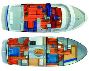
Our target market
includes successful business people and corporate presidents. They are well educated, well informed, and
generally experienced boaters either from pleasure boating, commercial marine
or Naval backgrounds. They intend to
live aboard and cruise long range both, offshore and coastal. Essentially they are looking for a “two
bedroom condo” on the water, but one with specific performance features. Good access to reliable mechanical equipment
is a must including full standing headroom in the engine room. They prefer naturally- aspirated engines,
dry exhaust, and keel cooling. Fuel
efficiency and extensive range at reasonable speed are key factors. Seakeeping and range of stability are
important issues; these are virtually all the characteristics that would be
required for any proper offshore vessel.
We set our goals at the following:
§
Super fuel efficiency
§
Range 3500 miles at 8
knots cruise with reserve
§
Top speed light loaded
of 12 knots for local fast cruising
§
Privacy between
staterooms
§
Aft full width
stateroom with walk around standard queen size berth
§
Midship guest room/den
with standard queen size berth or two standard single berths
§
Each cabin to have its
own wc, sink and shower
§
Forepeak fitted out for
storage and/or workshop as it is unsuitable for sleeping at sea.
§
Stand up headroom in
the engine room
§
Large main salon
§
Practical, good sized
galley with extensive storage
§
Separate eating and
lounging areas
§
Limited number of
vertical steps on each deck
§
Good initial stability
combined with a good sea motion
§
Long range of ultimate
stability (through 180 degrees if possible) without ballast
§
Collision bulkhead,
watertight bulkheads and engine room door
§
Effective, economical,
simple roll stabilizing system
§
Good styling and market
appeal
§
High quality yacht
finish
§
Modest draft
Pricing was not a major
consideration in the design goals, although it was taken into account when
planning the construction of the vessel to utilize efficient methods of
building. The vessel is priced to meet
the current market for similar boats of this type. It was felt that to price too low would infer that the vessel was
of inferior quality, and to price too high would result in reduced sales.
DESIGN
Hull Design
The hull design is based on the
essential characteristics used for a sailboat (or motorsailer), combined with
the effective hull form of a lobster boat.
The operating speed of a trawler yacht at long range cruising speed is
not too much different from that of a fast sailboat. The round displacement hull form moves through the water with the
least amount of fuss to show it’s passing.
Combine this with the occasional need to approach semi-displacement
speeds and you have a hull which must operate efficiently over a wide range of
speed/length ratios. By mixing in the
finer features of a lobster hull with the rounded sailboat shape, this
successful blend is achieved. In
addition the vessel has to have a smooth rolling motion with good seakeeping
abilities, and again the sailboat and lobster hull forms are a good blend for
this. Add to this a large spray knocker
running all the way aft and you have a vessel which is very dry on deck, has
large interior volume, and excellent stability characteristics. This form also has a natural roll dampening
ability.
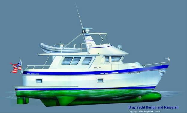
PRINCIPAL PARTICULARS
DESIGN Karvi 47
DATE July 1998
CLIENT Karvi Maritime LLC
LAUNCHED March 2000
LOA 46' - 9"
LWL 40' - 10"
BEAM O.A. 16 '- 0"
BEAM W.L. 13' - 0"
DRAFT 4' - 6"
DRAFT (HULL) 2' - 9"
DISPLACEMENT 47,000 lbs. (S.W.)
half
loaded
Speed
Nozzle
Also called a ducted propeller, the
speed nozzle is built around the propeller to increase the efficiency thereby
increasing the speed of the boat. By
directing water in the tunnel to the propeller blades you are forcing more
water against the blade thereby producing greater thrust through the
water. This nozzle is a further
development from the “Kort nozzle”, which was designed for maximum thrust at
zero knots. The high efficiency speed
nozzle is an airfoil ring around the prop.
It is like the “Kort” but thinner in section, designed to increase
thrust at higher speeds with much less induced drag. This arrangement combined with the tunnel and a large diameter
highly skewed propeller allows the propeller to run at a very slow rpm thereby
increasing propeller efficiency.
Besides increasing speed there are three other very
significant benefits of the speed nozzle.
These are reduced cavitation, reduction in propeller noise and provision
of added protection to the propeller blades.
Cavitation occurs when low pressure develops on the
surface areas of the propeller causing a breakdown in the boundary layer of
water flowing over the blade. A vacuum
develops along the leading edge turning the water to vapor. When these tiny pockets of air collapse back
against the propeller a high screeching noise results as well as pitting of the
propeller surface. This usually occurs
at higher propeller loads and/or higher propeller rpm. The nozzle decreases this cavitation by
containing the water mass, increasing the pressure, and controlling the outflow
of the stream.
A propeller nozzle can also decrease noise within the
boat. The tips of an open screw
generate a vortex interacting with the hull causing noise and vibration within
the boat. A nozzle directs the water
out the stern away from the hull, reducing the rumble against the hull and
making for quiet running.
An additional advantage of the ducted prop is the
protection it gives to the propeller blade.
Nobody plans on hitting underwater hazards with their propeller, but
accidents happen. The protective
ducting around the propeller serves as a protective casing guarding the blades
against damage.
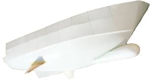
Bulb Design
The primary purpose of the bulb is
to allow the craft to slip more easily through the water by reducing
hydrodynamic drag. Vessels fitted with
a bulb benefit by what is known as wave cancellation or destructive
interference of the combination of the bulb and hull generated wave patterns. The wave form created by the bulb is
generated in such a way as to partially cancel the wave train created by the
hull. In effect, the bulb is helping to
relieve the dynamic pressure pattern around the hull, so that the integrated
effect is to reduce drag. With very
full-bowed vessels, such as tankers, the main effect of the bulb is to reduce
wave breaking and flow separation. Both
of these phenomena represent turbulent flow effects and if these can be
reduced, the result will be an overall reduction in resistance (drag) of the
vessel. A bulb also has the additional
benefit of reducing bow accelerations, this results in significantly improved
habitability in a seaway.
With trawler type hull-forms, such
as the Karvi 47, a bulb reduces drag by wave cancellation. There is also a reduction of wave-breaking
and flow separation on the more full-bowed vessels. In addition, there is the important effect of squat reduction at
the higher speed/length ratios. As a
vessel increases speed above a speed length ratio of about 1.3, it begins to
squat, or take on significant stern trim.
As speed is further increased, the trim increases to over 3 or 4
degrees, leaving a large stern wave, and high resultant drag.
The parameter of major importance
with respect to powering is the speed/length ratio, V/L ½ , V =
speed in knots, L = waterline length.
Most trawlers operate in the speed-length ratio range 0.7 to 1.7, which
is ideal for bulb applications. As the
so-called hull-speed is approached (V/L ½
= 1.3) these hull-forms tend to “squat” or take on significant
trim angles, with attendant large increase in resistance. A well-designed bulb will help to delay
squatting as the hull-speed is approached and result in significant resistance
reduction (of the order of 8 to 10%).
This translates into significant fuel savings (and also reduces the
greenhouse effect as a side benefit).
What are the design parameters that
influence effective bulb design? For a
given vessel, it must operate in the speed/length ratio envelope from
approximately 0.7 to 1.7 (this is not a fixed range but is appropriate to
trawler type hulls). It should be noted
that there is some evidence that the powering benefits of a bulb can extend up
to speed/length ratios of up to about 2.5 but design data is lacking and may be
applied only to special circumstances.
Bulb Geometry
Next, the proportions of the bulb
must be defined. Bulb geometry and
dimensions are influenced by the expected speed range, operating conditions,
hull geometry, block coefficient, prismatic coefficient, entrance angle, depth
of forefoot, bow overhang and anchor location.
Each of these variables puts limits on the form that the bulb can take.
Many trawler hull-forms are amenable
to a successful bulb design. The main
bulb geometric parameters are: cross-sectional area, and length forward, beyond
the intersection of the stem and top of bulb.
Generally, bulbs are referred to by the ratio of their cross-sectional
area to the area of the ship mid-section.
These values can vary from about 12% to 22%. The bulb length (distance the forward-most end extends beyond the
upper stem/bulb intersection) can be expressed as a percentage of the waterline
length and can vary from 3% to about 8%.
In most cases, a longer bulb works better for trawler hull-forms, but
important considerations of anchor handling, docking and maneuvering usually
limit this variable.
Bulb cross-section influences the
size of the wave that is generated, while bulb length determines the phase of
the bulb-generated wave. Optimal bulb
design is achieved when these two factors are tuned to act in unison to
minimize the net wave system of the hull.
Another important parameter is depth
below the surface. Considerations of
draft variability usually determine this value. As a rule of thumb, the upper surface of the bulb should remain
15 to 25 % of the bulb diameter below the still waterline. On a trawler hull if the bulb is too deep it
will not be of much benefit in reducing wave drag, and if it is too shallow it
may broach the surface at higher speeds.
Again, a balance must be attained.
The forward end of the bulb can have
a spherical or an elliptical shape. The
cross-section can be cylindrical, heart-shaped or of varying cross-section
along its length. Sea-keeping
considerations usual determine the shape factor. Careful fairing of the bulb into the existing hull as well as
around the thruster ports must be performed.
It is our practice to scallop all thruster ports to prevent turbulent
flow developing on the after side of the port, (possibly disrupting the
beneficial effects of the bulb).
Preliminary Powering
Estimates
Applying the above principles to the
bulb design of the Karvi 47 resulted in a bulb which was estimated to give a
drag reduction of approximately 10 percent at top speed. The preliminary powering calculation was
performed using an algorithm developed by Calisal et al, and published in the
SNAME publication, Marine Technology.
The algorithm is based on the “UBC Series” of trawler hull forms and has
been found to provide reasonable accuracy for preliminary estimates of powering
performance of trawler hull forms operating at displacement speeds. Estimates of the effect of the bulb on
performance are done using a proprietary algorithm based on empirical data from
bulb retrofits. Figure 1 plots the
results of these preliminary estimates.
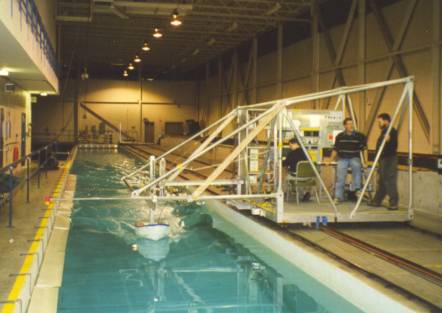
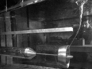
OUTDOOR MODEL TESTS
Outdoor model tests were conducted
to verify initial performance estimates, as well as to refine various aspects
of the design in a timely and cost-effective manner. A 1:8 scale model was constructed using a strip-plank
method. A removable bulb was fashioned
together with removable keels. This
provides for the ability to evaluate the effects of these various appendages on
the performance of the design relative to the bare hull. It should be noted that at this time, no
representation of the nozzle was tested.
For the outdoor tests, the model was
carefully ballasted to the scale 47,000 lb. displacement and towed using a boom
apparatus attached to a tender.
Resistance was measured using a digital force scale attached to the
towline. Running trim was monitored
using a digital trim indicator, with speed through the water measured using a
digital rotary speed log. Video was
also recorded for all test runs.
Results of Outdoor
Testing
The powering results of the outdoor
tests are presented in Figure 1. As was
to be expected with any outdoor model test program, there is some scatter in
the data, but the general results compare well with the predictions, and
confirm the general trend in the powering curve.
The benefits of outdoor testing
become evident through careful observation of the model at speed. Details of bow and stern waves, midship
hollow, and effectiveness of the spray knockers can be observed and recorded at
length on video. The tests confirmed the
effectiveness of the bulb in reducing squat, and thus resistance at speed. The tests also revealed a more optimal
location for the stabilizing keels.
Other changes made to the initial design were to fine up the entrance
angle slightly and refine the tunnel geometry.
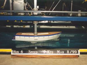
MODEL TESTS AT THE OCEAN ENGINEERING CENTRE
The outdoor tests provided important
information and guidance for the final design.
As a result, a much better design was achieved economically, without
spending large sums in a model test facility.
Tests in the model towing tank would be limited to the final optimized
design and would largely be used as input to the design of the novel propulsion
system.
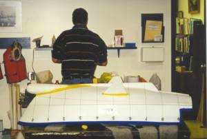
The prescribed modifications were
made to the initial design and the resulting model was used as a plug for a
female mold. A fiberglass and foam
model was then made to be tested at the Ocean Engineering Center of B.C.
Research Inc., in Vancouver, Canada.
The model was tested at a scale 47,0000 lb.
displacement, in fresh water.
The following configurations were tested:
Table of Model Test Configurations –
Ocean Engineering Center
|
Configuration
(at 47,000 lbs)
|
Static Trim
(Degrees)
|
Description
|
|
A
|
0.00
|
Bulb and keel at design location
|
|
B
|
0.00
|
Bulb only
|
|
C
|
0.00
|
Bare hull
|
|
D
|
0.00
|
Bulb, keels swapped, moved aft 8 inches full scale
|
The results of the tests are
presented in Figures 2 to 5. These
results confirm the preliminary powering predictions while providing the
necessary accuracy for selection of installed power and detailed design of the
speed-nozzle propulsion system.
It is interesting to note that the
effect of the bulb on running trim is marked at speeds over 9 knots, and the
result is largely responsible for this trawler hull form being able to achieve
semi-displacement speeds given sufficient power.
Listed below are some of the full-scale performance figures
for the design at a nominal 10-knot speed.
From the above figures one can see
that with the addition of the bulb the power is reduced by approximately 10 %
at 10 knots. With the addition of the
Bray keels this powering advantage over the bare hull becomes about 4 %, giving
an EHP of 89.8 hp at 10 knots, which still very low for a hull of this length
and displacement. It should be noted
that while the Bray keels add drag, it is considerably less than the drag of
conventional “flopper-stopper” type or active fin type stabilizers.
DISCUSSION
ON CONSTRUCTION
Fiberglass/foam
core construction was chosen for manufacturing the hull and
superstructure. Although steel and
aluminium were also considered, fiberglass had the majority of the benefits for
this application. PassageMaker
Magazine’s market study had shown about a 20% interest in steel, a small
percentage interest in wood and aluminium, and by far the greatest interest
still in fiberglass. The boating public
have really been sold fiberglass as a construction medium for yachts, over and
above everything else. In many ways
this is because yachts typically are relatively poorly maintained (fiberglass
is virtually maintenance free) and because fiberglass lends itself so well to
mass production techniques. In addition,
it is easier to get compound curves and detailed “yachty” styling lines into a
component without relying on highly skilled labour. Once the original part is made by a skilled craftsman and a mold
is taken off, the process of duplicating that part becomes a simple procedure.
Foam cored
fiberglass was chosen for greater strength and safety. Although there may be considerable debate
about that statement, our experience has supported this conclusion. The foam core spreads the shock loads
between the outer skin and the inner skin.
Damage to the outer skin is dissipated in the core and the inner skin is
almost never ruptured. Also the foam
core adds positive buoyancy should the vessel be completely flooded, adds a
certain amount of sound deadening, and heat insulation. It is important to use a closed cell cross
linked PVC foam to prevent moisture absorption. Extra care is required to make certain that the foam is in complete
contact with both skins in the molding stage for without proper contact all the
advantages of this material are lost.
The down side is that foam core is expensive, requires more labour than
solid glass, and requires a somewhat more skilled work force.
With the
surprising interest in steel for this type of vessel a study was undertaken to
determine what were the features people expecting from this material. The primary interest was abrasion resistance
should the boat go aground and ramming strength in a collision situation. We felt that the foam core and collision
bulkheads handled the latter but needed an additional feature to combat the
former, so a steel shoe was laminated into the keel. This 1” thick flat bar is 6” wide and runs the full 30 feet of
the keel. It is laminated in the first
few layers of fiberglass so there is no need for fastenings to penetrate the
hull. This was then backed up with 1 ½”
of solid fiberglass, giving a substantially stronger keel section than the
norm.
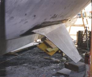
The bow bulb is
laminated of solid fiberglass for strength and ease of construction and bonded
to the hull as a separate watertight appendage. It has great strength due to
it’s shape and heavy laminate and essentially acts as a collision bumper, as
well as contributing to reduced resistance and improved seakeeping.
The high
efficiency nozzle (speed nozzle) is fabricated from stainless steel for
strength and ease of construction.
Stainless steel is a must for nozzles for resistance to deterioration
from propeller tip erosion. The nozzle
has a precise section shape which gives unique performance features. This is achieved by making up sections of
the circle and welding them together to make the complete ring. The hollow foil-section rudder is also made
of stainless steel over a stainless shaft.
The stabilizing bilge keels (Bray keels) are a foil
section fabricated from aluminium plate.
The depth of the foil and narrow cross section make it impossible to
construct out of fiberglass without assembling two halves, a system which
raises concerns about achieving a satisfactory joint. An accurate section shape is required to get the hydrodynamic
effect from these foils so the fins were designed in the same way as sailboat
keels, fabricated, and bolted onto the hull on a reinforced solid fiberglass
area. The structure is strong enough
for the vessel to sit upright on it’s own bottom.
SEA TRIALS OF FIRST PROTOTYPE
At this time the authors are
awaiting launch of the first boat. Report of sea trials will be delayed until
mid June. Powering performance,
seakeeping, noise and vibration as well as maneuvering will be investigated.
CONCLUSIONS AND DISCUSSIONS
This paper reports the process of
development of a production trawler yacht.
Presented are the necessary steps to achieve a successful design. These include market analysis, preliminary
design, testing and development, use of advanced construction techniques, and
final commissioning of the first prototype.
From the beginning, the goal was to
produce a trawler yacht that incorporates the latest technological advances
that would result in a safe and fuel-efficient design. Technical innovations borrowed from the
commercial marine industry such as the bulbous bow and speed-nozzle propulsion
system were applied to the design of the Karvi 47. The latest in construction methods and materials technology were
used in the building process. The
result is a trawler yacht that can be economically built and which exhibits
performance that is significantly better than existing comparable craft.